Of course, I said yes. As with many projects that are done for movies or TV, I didn't really have the time or inclination to document this build as I was going, because it had to be done so quickly. My time was better spent actually working on it, rather than photographing it and blogging about it.
Fortunately, along the way I would occasionally snap a photo with my phone to send off to the production team for feedback or validation. This blog post reveals those photos.
But let's start at the very end. Here's Betty as she showed up on set:

What I really like about this particular photo is it shows how much emotion can be conveyed by what is essentially a puppet. This is definitely a "Betty is NOT amused" moment. I'm just really happy and proud at how well this turned out, and I feel that this photo really captures what Betty is capable of.
If you'd like some more context for this blog post, please check out episode 1 of the web series. In a funny twist of fate, Betty's face is used as the thumnail image for this episode, with her eyeball replaced with a screen cap of an actor. Yay Betty!
Take note that my goal was not to reproduce identically the lil' fellers seen in the second Portal video game. Though of course the design ethic was meant to be similar, but the direction I got from Zack at Wayside was that betty was a different model, and was maintained much better than the spheres seen in Portal II. This gave me a little flexibility in some of the details. Of course, the goal was to get it as close as possible, within the time and budget constraints I was given.
Like many projects, this build started with a lot of drawings I did in Adobe Illustrator. I found some reference pictures online, mostly in-game screen grabs. One showed a sphere from dead on center. I scaled that in illustrator and measured out all of the primary details. For example, the size of the main eye compared to the body, the eyeball, etc.
Here's how the build started:

This is a poor-man's rotocast that I made out of a globe I purchased from Target. My original plan was to buy plastic or plexi-glass sphere from someplace like Tap Plastics, but it turns out that they are hard to find and prohibitively expensive. The globe cost me like twenty bucks. I cut the globe in half along the equator, then lined it with packing tape. This made it somewhat waterproof, and therefore resin proof. I sealed the globe back up along the equator using tape, then cut a pour hole in the top. I dumped some resin in, and slushed it around. Once it cured, I separated the globe and peeled it off.
The remaining sphere needed a lot of work, as the inside of the globe had a lot of uneven texture to it from all the tape.
Realizing that not all of the globe would be exposed, I tended to the parts that would be. The circular openings were cut using a compass that I had left over from high school, a dremel tool, and a coping saw.
Here's what the primary sphere looked like after a lot of sanding, puttying, and a little bit of detailing.

I did a bit of research on the spheres seen in the game, and they are impossibly complex. By my reckoning, there are three nested spheres, each of which moves independently within the others. This would be impossible to accomplish, especially within my time and budged constraints. I settled on attempting to reproduce the look of the sphere, though eliminating some of the nesting functionality.
One of the recognizeable traits of the spheres is their handles. I originally had some plans to make them out of styrene, heat them and bend them to shape, and make them all pretty. BUT with time running out, and knowing how things in real life look differently on screen, I went with a quick and dirty approach using wooden dowel rods I got from home depot. I cut them to shape, including the angled bits, then glued them together. Not pictured, but I then brushed resin on them to add strength and hide the seams. I did some sanding and puttying to clean them up a bit. Ultimately, I was never really happy with the handles, but they ended up looking really good on screen.

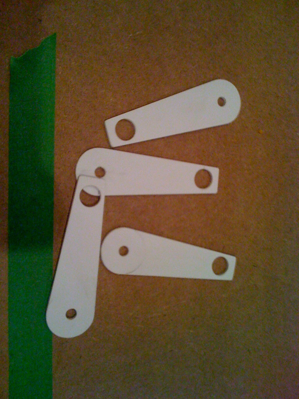
The handle mounts were made from sheet styrene. I drew up a pattern in adobe illustrator, printed out four copies of it, then transferred them to sheet styrene. I then cut them out using a coping saw, x-acto blades, and a drill press. Like many other of the finer details on the in-game spheres, I ended up simplifying the design for Betty. Extra details were eliminated, or complexities were simplified.
As mentioned, the spheres in the game are a series of nested spheres, which I had chosen to replicate the look of. The primary sphere has two toaster-like slots on it, one on top and the other on the bottom. In the game, these are kind of open, revealing the inner workings and structure of the sphere. I thought a lot about how to accomplish this, but the problem with it was that it would mean the entire sphere would need to be held together by just a few tiny and thin pieces of metal or resin. Knowing how puppets are handled on set, and the rigors of on-set handling, I decided something like this was a poor choice. I instead decided to carve out a recess, and then fill it with some ribbed styrene that I had left over from my Multipass project.
Here you can see where I've marked off the recess that I'm going to cut out.

Using my dremel tool and router attachment that I got up and running for my Arkham City Grapple Gun project, I hollowed out the cavity. Note that it follows the contours of the sphere. Well, roughly. Thank you router!

Here I'm test fitting the ribbed styrene. I remember taking this picture so I could show Zack what I was doing. This was a pretty big departure from the in-game sphere, and wanted to make sure he approved.

Here's the final strip installed.

Next step was to build the outer sphere. I went back to the globe I used as a master for my main body sphere. Since I knew that globe had the proper outer and inner diameter for my existing main body, I simply used that. I cut it up into pieces that were the correct shape. I then brushed resin on the halves to give it some stability and a sandable surface. Then I glued the pieces onto the main body. In this picture, you can see where I'm doing some work with spot putty to smooth out some of the flaws in the resin coated cardboard outer sphere parts.

One of the things I experimented with for the outer sphere and for the eyeball was a poor-mans heat forming deal.

I don't own a vac-form machine, which is a total bummer, but I figured if I weighed down the edges of a piece of styrene then hit it with a heat gun, it would form to the shape underneath it. It did not. lol. Still, this is a good example of my experimenting with different techniques to get the desired result. Much of the project was like this. A lot of experimentation, and finding interesting ways to solve problems that I had never encountered before.
Up until this point in the build, the hardest part was getting the sphere spherical, and the nested sphere fitting properly. Because that stuff is SO precise, it was really hard to get right. Turns out, this was nothing but preparation for the nightmare that awaited me on the eyeball.
My research revealed that the eyeball was also really quite complex. Not only was it a series of layered concentric circles, but the eye lids blinked independently. For example, the top lid could lower all the way down without the bottom lid moving. Or vice versa. Or the top one could come half way down, with the bottom one coming all the way up. And they didn't have to meet in the middle. OY! Again, I kind of had to choose my battles, but for the puppet to have any kind of expressiveness, I felt that I really needed to get this part right.
If I had my way, I would have used a laser cutter to cut out all of these infernal circles. That way they would have all been perfect, they would have been done quickly, and they would have lined up perfectly.
Unfortunately all I had was my tools on hand, which included the aforementioned protractor that I've had for more than 20 years. And they said I'd never use high school algebra!

Using my drawings, I extrapolated measurements for all of the circles. Then it was just a matter of cutting them out, one by one. I would draw them using my protractor, cut out the inner part with a coping saw, then use files and sandpaper to get the circle to size. Very painstaking work, as I wanted it to really look like a machine made robot. Not a wonky hand built puppet.
Here's a shot of the layers of styrene, surrounded by the frame.

The frame was another piece of work too. When I cut up the slush cast sphere I made from the globe, I had some leftover parts. Including the part that used to fill the main hole. I ended up extending the edges of it, and filling in some messes I made when removing it, and this served as the frame.
Bouncing back in the process a little, here's what the eye frame looked like inside the spheres. Note that those rings on the side are actually the main bodies of some tap lights I picked up at Home Depot. As luck would have it, their outer diameter matched perfectly to the drawings I had made in Illustrator. That saved me the trouble of having to fabricate those. Which is a great thing as I had no idea how I was going to pull that off.

After some work and some paint, along with some scribe lines cut into it, here's how the eyeball was coming together. The pupil graphic was designed by Zack Finfrock. In this picture, that's just something I printed out on my computer to show them how it was coming along.

One thing you cannot really see from this picture is that the black rings in the back are actually separated from the frame by about a half an inch. They are supported on the edges by some styrene. This was to allow the eye lids to slide up and down behind the frame, but in front of the circles. Yikes, my head is spinning again just thinking about it.
A few scribe lines, some paint and some clean up later.

At this point in the project, my brain really started to come unravelled. It was time to take on the most challenging piece of the entire project, engineering a control arm for the puppeteering of the eye. I had some pretty clear requirements. First of all, the entire eye needed to move freely within the sphere. It needed to be able to move up, down, left right. It also needed to be able to rotate a bit in either direction. And move in and out within the sphere. And when unattended, it needed to maintain a respectable position. It also needed it's own light source. The eyelids needed to blink, as discussed earlier. Not just blink, but be puppeteered. Oh, and the eyelids needed to be in an closed position when "idle". This said to me that there was going to be some rubber bands involved to provide tension on the eye-lids.
All of this was a LOT to consider. After MUCH thinking about it, strategizing, and doing pencil drawings, I finally came up on a solution that I thought just might work.
I started of by fabricating a stand that would hold a flashlight in place, suspended a certain distance away from the pupil. I did this all in MDF, as it's pretty easy to work with, is available in different thicknesses, and is strong enough for my needs.

I then built two arms, each of which would be attached to an eye lid. They had pivot points on the base that I just built so that the eye lids could open and close.

This is the whole thing put together. You can see the pivot arms attached to the eyelids, and how the flashlight is suspended above the pupil. You can also see the rubber bands that are going to provide tension on the eye lids, keeping them closed when not puppeteered.

Here's how it looks from the other side.

With that behind me, I got to fitting the eye inside the sphere. Here's how it looks so far.

After that, it was really just a matter of a paint job and some details. And of course some more clean up. There was also a last minute requirement that it have a pole coming out of the top of the head so that it could run on a rail. For something that significant, it's an interesting foot note that I totally forgot about it until a couple of days before shooting.
Here's a picture I took of my workbench while working on the eyeball mechanism. I don't think it's ever looked so hectic.

Lastly, here's a picture of me on set, during filming. The portal gun itself is mine, which is one of the licensed replicas that was offered a while back. Now it's screen used, which makes it 100% screen accurate. Hehehehe. I'm standing in front of a companion cube, fabricated by my good pal and fellow builder Kai Norman. Great work, Kai!

Thanks for reading this write up. I hope you enjoyed it. Please be sure to check out the Aperture R&D webseries, and anything else created by the good folks at Wayside Creations.

.jpg)


